Multi-View Image Stitching based on the pre-calibrated camera homographies.
Image Stitching is a common problem that has out of the box solutions. I stumbled across a need to construct a Multi-view image stitching system from scratch when I was doing my final project. Image stitching can only be done in two scenarios
- When all the images were taken only differ by the camera rotation
- When scene being viewed a planar scene or nearly assumed to be a planar scene (The case of a quadcopter viewing the ground below at a great height)
The scenario I was interested in is the second one since we had a 4 camera system setup for viewing the mice. This project was done for a neuroscience lab and the setup looks as shown below and the need was to construct a high-speed image stitching system

Image Stitching process
When you upload images for stitching to a black box software or use OpenCV to stitch images, the following steps happen.
- Feature detection in each image
- Feature matching
- Homography estimation between images
- Transformation of all images to a common plane.
- Blending of images at the transition points.
- Projection of the stitched image onto a different surface (like a cylinder, sphere etc..)
If you are not sure about the steps mentioned above, I urge you to stop reading and read a little more before proceeding further with the post.
Simplifications for speed up in a static camera controlled lab setting:-
In my case, I am only interested in the first four steps since the last two steps are more about matching the human experience of viewing images. For our laboratory purpose, where our sole interest lies in coming up with a high-speed image stitching mechanism for viewing our mice experiments, blending and projection are nice to have mechanisms and hence were ignored to retain the speed of stitching. Moreover, this system is a lot simpler than a typical general-purpose image stitching pipeline: the cameras are mounted in a physically static location, and hence, the homography between the cameras never changes (unless someone physically moves the cameras, which is not the case here). Therefore, homographies once estimated will never change forever, and therefore, during online operation assuming we have homographies pre-calibrated, the only step to create a stitched image is step 4 i.e., the transformation of all images to a common planar view.
How does it work?
We can do a calibration routine to figure what is the homography that connects each camera image to the common hypothetical stitching plane. Once this is figured out, we have all that is needed to do image stitching for the given system. In order to figure out a homography, we need at least 4 point matches since a homography has 8 degrees of freedom.

How do get at least 4 point correspondence between each camera image to the hypothetical stitching image plane? Place a checkerboard in the field of view. In my case, I was interested in a stitched image that resembles more a top-down view of the plane being viewed. It's easy to detect the corners in a checkerboard and once detected, we can manually assign positions to each of the corners. In the top-down view of the plane, we can assume axes parallel to the checkerboard axis and it is trivial to assign values to each corner detected. Note the distance between each corner in the manual assignment determines the scale of the image. (Note: It is also possible just to associate these corner points from the second, third, and fourth camera images to the first camera image. Here, the first camera image will act as the stitching plane that we desire. But I prefer the former to impose a top-down view of the plane and hence, ended up using the former strategy).
A note for specifying the perfect image size
If you have been paying close attention till now, there is a natural question that must have popped up in your mind: How to determine the size of the stitched image. Well! You can but you don’t have to: There is a shortcut. The shortcut is to specify the stitching image to be large enough that all pixels from all four camera views after transformation still lie within the image. This can be specified by thinking about the camera configurations a little. In my case, the cameras lie in a sort of rectangular configuration so the maximum size that the stitched image could reach is 2x the size of one of the camera images since the cameras are mounted orthogonal to the ground plane. But you can figure this out by viewing the stitching image and increasing the image size when all four images fail to make it to the common view. Once the stitched image is done, we can loop through all pixels to determine the top left and bottom right pixels. Loop through all pixels and determine the minimum x, maximum x, minimum y, and maximum y index of pixels that hold a non-zero value. (min_x, min_y) gives you the top left corner of the image and (max_x, max_y) gives you the bottom right corner. This is the region of the stitched image that contains the actual image and the rest of the area is empty or all zeros. So the final image size required id (max_x- min_x, max_y- min_y).
Are we done? Not so fast. The homographies we have initially estimated transform the camera images from their view to the bigger stitched image that we arbitrarily specified. But now we have changed our image size to reflect the true size of the stitched image. In order to transfer the pixels to this cut-down image, we have to modify the homographies. The new homography H differs from the estimated homography h by a translation T. But we know what this T matrix is. This T matrix is shown below
T = [ [1, 0, -min_x], [0, 1,-min_y], [0, 0, 1]]
H = T * h
Modifying each of the precomputed homographies by this translation matrix premultiplication fixes the problem. The new homographies H can now be used to transform each image to the smaller stitched image view.
Results and Troubleshooting:-
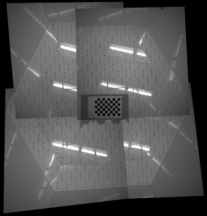
The first time I put the whole code into action, I got the most depressing results.
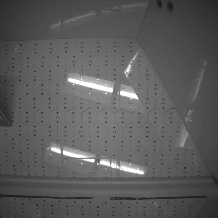
If you have worked with actual camera hardware before, you should be immediately able to comment on the problem here- I was so dumb not to correct for lens distortion. There was definitely some finite and observable lens distortion here, which are non-linear and can never be capture by our homography estimations. To give you some idea, this is how the images looked before and after lens distortion correction.

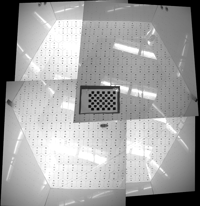
So, I gave the image stitching pipeline a run after lens distortion correction and the results looked better but not perfect.
The reason that there was still some noticeable misalignment is that I was using a very small checkerboard that was visible only within a very small area. I was trying to place a checkerboard at the overlapping field of view of all four cameras so that the homographies to the common planar view can be obtained but the downside was that I wasn’t using the whole field of view to improve my homography estimate. If I placed a bigger checkerboard, I had to come up with some strategy to associate each corner with a row and column index. In the above image, the checkerboard is placed such that the top left corner of the checkerboard stays the top left corner in all the images, and hence, finding the row and column index for each corner is easy. In order to bring a bigger checkerboard to the play, I needed an easy strategy for the corner association. One simple solution to this problem is a Chauro board. A Charuco board has an Aruco marker and a chessboard. The Charco maker enables identifying each corner with a pre-determined index thereby allowing us to use a bigger board that is only partially visible in each camera view.
But calibrating based on the Charuco marker gave me the perfect results.
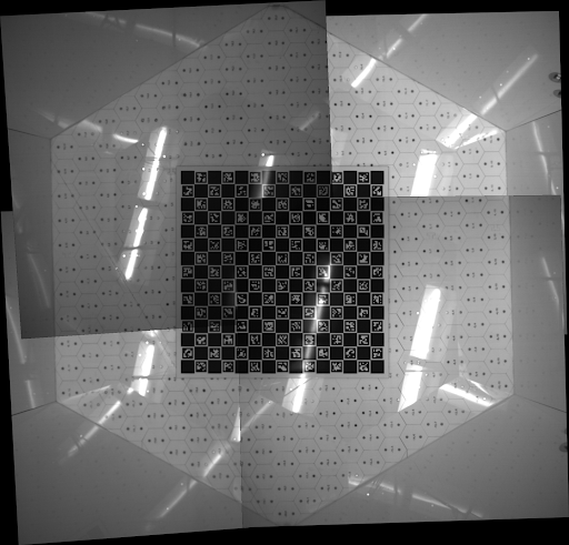
Finally, you can lay back and enjoy the results of your work
One thing you can notice from the image is that some transitions in the stitched image look discontinuous due to the 3D obstacles that are placed in the maze. This is due to the violation of our flat plane assumption and hence, is an expected result. To reduce this effect, the camera has to placed at a higher height or the obstacle height has to be reduced.
